New PCBs and P.I. Control

Analog servo driver and analog proportional and integral control board. I built six each so I can use these as modular building blocks in my prototypes.

Keeping with my dedication to analog circuitry, I have decided to experiment with analog PID control introduced into the signal flow of my flapping mechanism. I developed an analog proportional and integral (P.I.) control circuit and designed new PCBs in a modular form. With these in hand, I will update my prototype wing mechanism and add these circuits to observe their behavior.

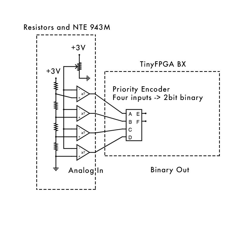
Each servo has an internal feedback potentiometer which I can tap off of to read that same analog voltage. Using some buffering and amplification, I can compare that voltage to the desired state and process the error. This is the first stage of any PID control. I then use a single integrator op-amp with some amplification to do a combined P.I. control stage. I experimented with the derivative “D” stage of PID, but I didn’t feel this stage added value or behavior to the circuit I liked. Because each servo already has its own feedback control system, I think this additional P.I. control is working in tandem with the built in control of the servo.

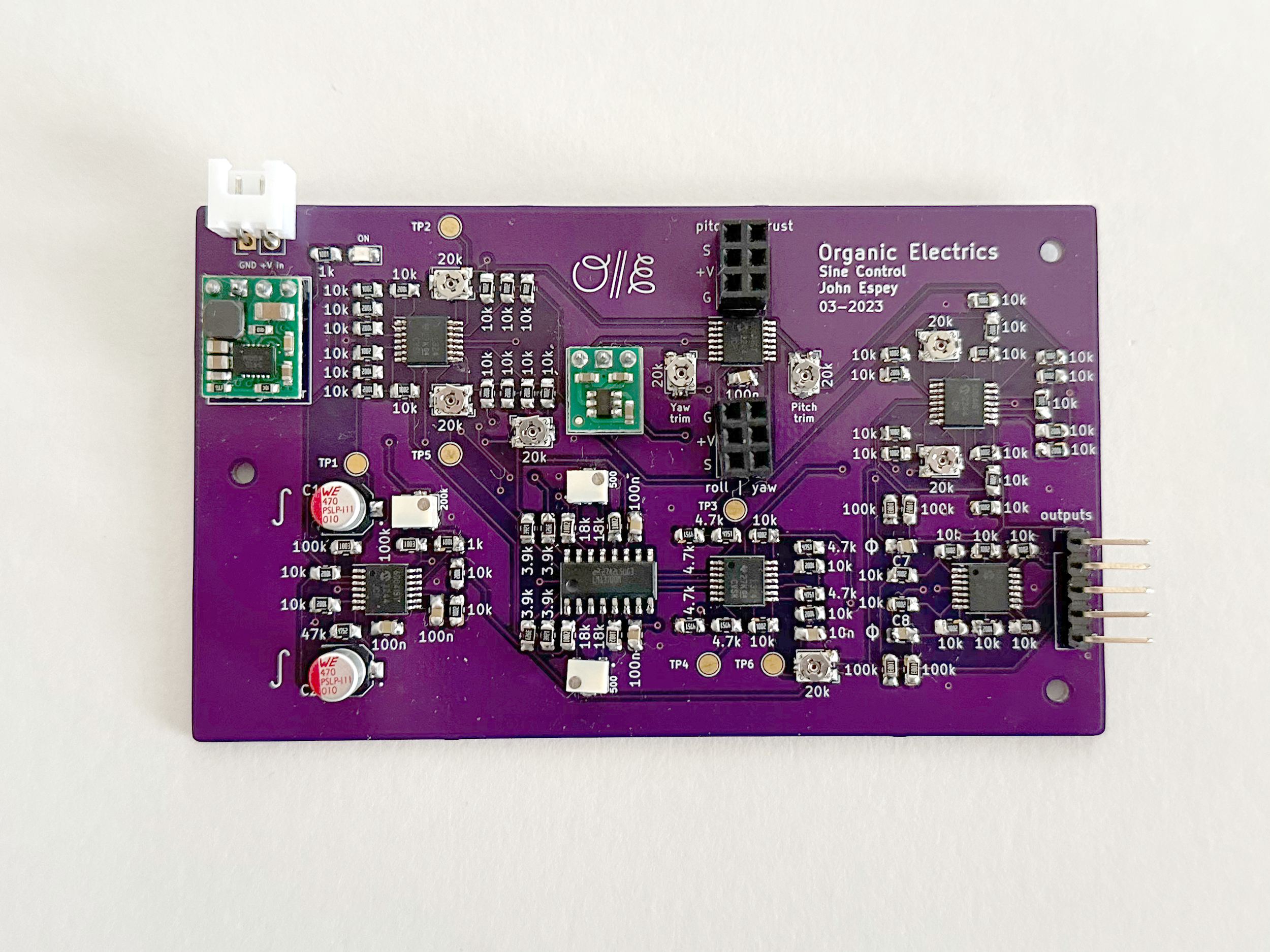
Sine control board, four servo generator boards, and four PI control boards. All PCBs from OSH Park.

My Sine Control board was originally designed to inject sine wave signals into my RCTx device. This did work, but my prototypes still depend on a large power supply and need to be clamped down, so I don’t need wireless control yet. Also, I had an analog servo driver circuit in my back pocket from a great YouTube tutorial from w2aew. I decided I would prefer to use additional analog circuits to drive my servos which could take any input voltage signal. I adapted the servo circuit from w2aew’s video and created a PCB of it for use in my projects. I added more convenient servo power input pins, accepting the fact that I always need to provide a separate power supply to the servos. Servo motors can pull a lot of current and temporarily drop the power supply voltage. Also, some high power and high speed servos are capable of operating at seven or eight volts, and I would like to continue using the MCP600x op-amps, which max out at five and a half volts or so. With one servo driver per board, I ordered six from OSH Park and I’ll be able to use these for many prototypes in the future.

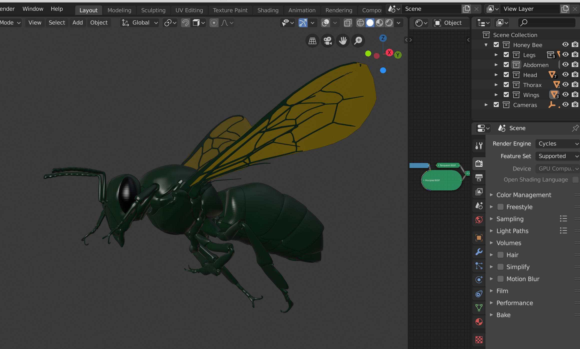
Now with analog sine signal generator, analog P.I. control, and analog servo generator, I have modular building blocks to use for prototyping more robotic mechanisms and giving them behavior. The P.I. control boards add a spring like quality to the movement of the servo, and it responds to being pushed out of position. I like this semi reflex type behavior a lot. I need to update my four wing mechanism and 3D print it. I wish to include small mounting brackets for these new PCBs too. The Sine Control PCB will stay on the desk though because it needs bulky input controls from joysticks and linear faders. I hope the new flapping behavior is more fluid and organic. If so, I will consider creating a more finalized piece by developing semi autonomous input controls and putting all of it into a single enclosure on the insectoid. Perhaps it could be a mobile or some kind of kite?

New Tool Allows New Opportunities

New tools can open new opportunities for the creative process. I am thrilled to announce that I will be constructing larger animatronic bugs thanks to a new addition to my workshop. I look forward to large butterflies, detailed bees, and new filament material options like TPU, LWPLA, and ABS/ASA.

Voron 2.5966 350mm build plate used to print larger wing veins.

At the end of July 2023 I made the decision to purchase a new 3D printer. I was considering several options, but the primary goal was to find something that was much higher quality and large. I really needed something that would allow me to print large insect wing veins. I settled on the Voron 2.4 with a 350mm square build plate. This is one of the largest build plates available other than a few models of Bed Slingers. However, I liked the enclosed design of the CoreXY, direct drive extruder, and ease of upgrade and fixability of Voron.

It took about one month from point of purchase to fully assembled. I immediately printed a very large butterfly wing and knew this was going to be worth the investment. With this printer, I should be able to make an animatronic butterfly (or some other insect) with a full 3 foot wingspan!

After some hiccups with printing before final tuning, I refined my wing vein model to be hollow, but very stiff. I did this by creating a triangular structure with the veins. I am already so proud of these new veins. Thanks to being able to use the updated Cura slicer, and the very accurate reliable movement of the Voron print head, the veins came out great. I am looking forward to gluing them to tissue paper and getting the largest, lightest, and stiffest wings I have ever created. I am hopeful these could indeed catch the air and wind and kind of glide or act as a kite.

I’ve also taken a turn at re-printing some of the honey bee parts I printed for the prototype. I had rippling issues on my Anycubic Delta printer, but now they are silky smooth and in natural PLA, allow me to paint them in transparent raw sienna to produce a beautiful honey color.

Sometime in the further future, I look forward to trying filaments like TPU and ABS for wings and body parts. ABS is not quite as stiff as PLA, but it recovers better after impact and bending. TPU is very rubbery and could be quite useful for flexible parts between the exoskeleton pieces. I am glad I started cheap and worked my cheap printer as far as I did, but now that I have a printer of such higher capability, I recognize that sometimes, good tools really do increase the capabilities a lot more!

Honey Bee Kinetic Sculpture Prototype

3D printed honey bee kinetic sculpture prototype

Lightweight PLA 3D printed honey bee kinetic sculpture.

This is a prototype 3D printed honeybee sculpture. I’ll describe the design process and the various components. Several improvements are needed before a final version is built.

The honeybee is roughly 8” or ~20cm from head to the tip of the abdomen. It contains servos, batteries, and a wireless receiver. The wings flap a full 180°. The legs articulate and the abdomen conceals the battery and receiver. After reviewing slow motion video of the wing flapping motion, I discovered the natural harmonics of the wings vibrate in an unrealistic way. I’d prefer to see a larger scoop motion in time with the wing flapping frequency. The parts are mostly printed from light weight PLA. The bee uses very compact, high-quality servos, and the 3D printed body is as accurate to real honey bees as I can achieve right now.

Line art render of the wing mechanism containing four servos coupled to four herringbone gear sets.

The design process starts by creating scale copies of the servos and hardware. Components I know I will need to use. Once those are modeled, I add the structural forms around them and design various linkages and attachment points. During this process, I start 3D printing these parts and assembling them to verify their design and strength. After several iterations, I settled on compact, strong, and fairly easy to assemble parts.

Mesh of honeybee exoskeleton used to create a 2D template.

Previously, I had modeled a honeybee exoskeleton and used to it to create 2D templates from the UV maps. I copied this model and scaled it to fit the servo mechanism. I used several modifiers in Blender to smooth and round the exoskeleton components. These smoother components work better for 3D printing. I printed the honeybee exoskeleton and assembled it by gluing small tabs of craft foam between the sclerites. The articulated legs have small axles of monofilament and give the bee a lot of life. The LW PLA material is quite weak and the legs snap near the joint. The abdomen is somewhat articulated as well because each tergum and sternum are attached inside with flexible craft foam.

While finally assembling this prototype, I discovered a variety of problem areas that will need to be addressed:

  • The wing motion doesn’t sell the realism.

  • 3D printed PLA is too weak for the leg joints.

  • The mechanism, batteries, and other peripherals take more space than anticipated.

  • The head is currently dead weight.

I think I could address each of these issues by updating the model and improving the compactness and strength. If I find a really solid design, I may invest in ABS or Nylon printing either at home or through a manufacturer.

Line art render of wing stroke mechanism embedded into honeybee model.

The servos are a steep investment in these prototypes. It is best practice to allow easy disassembly. The option to reuse the servos is more cost effective. Prices of servos range from $2 per servo to over $200 per servo. Having examined the $2 - $60 range myself, I can agree that you get what you pay for. The more expensive servos have considerably higher torque, they are faster, use precise gears, and have reliable feed back electronics. The housings are accurate, the cabling is decent, and the motors draw more current. Cheap servos are often very inconsistent, vibrate or oscillate due to errors in the feedback circuitry, and can jam on themselves due to poor gear and housing accuracy. However, I still recommend purchasing a bulk order of cheap servos, because they are a low risk way of testing very early design ideas. As the mechanism being designed evolves, nicer and pricier servos can be introduced, to verify the design is working as expected.

Continuing on the topic of costs, what surprised me is the cost of hardware. Several hundred M2-M3, and 0-80 size screws with nuts, washers, threaded inserts, and more added up to over a $100. McMaster has a large inventory and ships quickly, but even the tiniest of screws costs some money. It may be a good idea to avoid using hardware as much as possible.

One future project that I’m interested in exploring is designing parts that could be cut from flat even thickness materials. Several of the frame components are 4mm thick and could be laser or CNC cut. I have also previously used my honeybee model UVs to create foam templates to be glued together into 3D objects. Perhaps in the future, I may find it more economical to order these parts precut. Additionally, if I can borrow some design ideas that reduce the use of hardware, these flat materials may be able to snap or lock together without screws, further saving costs and weight.

Overall, this prototype was exciting to design and build, but I was disappointed by the resulting wing motion. As I reflect on the areas for improvement, I realize that my solutions may work better using a different model organism. I think a large beetle would offer more flexibility with component space, wing stiffness, and including robotics in the legs and head. Finally, this is the sculptural piece of this project, but there is an electronics piece that comes with a lot of complexity. I’d still like to design sensors and an analog computer to accompany this sculpture, so it is an autonomous robot of sorts.

New PCB Sine Control an Add-on for my RC Tx

I have created a new PCB I call Sine Control. It is an add-on for my radio control transmitter. It is placed in series with the joystick gimbals so that the radio transmits servo pulses based on the smooth sine wave output of the board. The joysticks control thrust, roll, pitch. and yaw. The Sine Control PCB outputs left and right signals and a phase delayed pair.

Radio Control transmitter, Sine Control PCB from John Espey, and 3D printed wing mechanism.

New PCB in front of an empty board, and my previous THT version.

I learned several lessons from the last PCB run and I greatly improved the circuit design. I compromised and accepted including a dual power supply. This allowed me to use an operational transconductance amplifier, the LM13700 OTA. Now I have an easy way to control amplitude with voltage. I also sourced common components like the MCP6004 and LM324 op-amps so my circuit design wont rely on obsolete parts. The board itself is also a quarter the size of my through hole board from last fall. SMD parts are superior in cost, size, weight, and availability. Also, the smaller boards are cheaper too. I used OSH Park to provide the PCBs.

Schematic of the Sine Control Add-on for a radio control transmitter. The circuit employs op-amps, an LM13700 OTA, and outputs four sine waves.

The circuit design was heavily inspired by audio electronics. The LM13700 OTA is often used as a voltage controlled amplifier (VCA). I used the same sine wave generator from my previous circuit which is the dual integrator with feedback. The thrust and roll input controls are summed or inverted to control the amplitude of the sine wave on the left and right sides of the wing mech. The amplified sine wave output is then level set by the pitch and yaw inputs mixing. This allows me to flap the wing on a gradient of no to large stroke angle. It also allows me to flap the wings forward of the body, or behind it. My theory is that in order to increase thrust, the frequency does not need to change, but the amplitude.

Sine Control PCB. Four inputs control the amplitude and level of inverted sine waves and a phase shifted pair.

Soldering these small SMD components isn’t too difficult. The resistors and capacitors are 0805 packaging, and the op-amps are TSSOP. What I did not anticipate, is the trim potentiometers aren’t cheap. The multi-turn closed trimpots in SMD packaging can be $3-4 each. It doesn’t sound like much, but for something the size of a Tic Tac, and combined with the price of other boards and parts, it adds up quickly. Instead of designing my own power supplies, I purchased two from Pololu. The step-down 5V regulator and the voltage inverter. These are quite small and only provide hundreds of mA of current. Op-amps take very little current and the entire board only draws 10-20mA. I did look to see if I could use the same parts and design my own power supplies. Unfortunately, Digikey and Mouser do not have the chips in stock. Supply chain issues are still impacting component availability. Thankfully these power supplies from Pololu were available!

PCB hacked into the back of my RCTx

Testing and trimming the circuit to output precisely the right voltage is laborious. Next time, I think putting in more effort to avoid excessive trim pots will help cut costs and save time. That is a major consideration in favor of a digital circuit. Digitally, one could just adjust in software and always have a consistent result. However, as I mentioned above, the entire board only draws 10-20mA which is just the operating current of a single micro controller. So we do get great power savings as a MCU would need additional components that would draw even more current.

Demonstration of the Sine Control add-on for a radio control transmitter.

Creating this board represents a major turning point in my craft. I had often wondered if I would ever get to the point where I was designing circuits and building them in SMD sizes. Now, I am here! From this point forward, I can explore even more complex signal circuits, flexible PCBs, custom board shapes, and embedded systems.

What I find so appealing about these signals is that they are a sine wave and my control inputs are all mixed to deliver behaviors instead of managing the positions myself. I followed a roughly video game like control input scheme. The left hand controls position of the body, while the right hand controls perspective of the body.

This flapping mechanism does not fly whatsoever. In order to tackle flight, I will need to greatly improve the weight, and wing designs. It is pretty heavy, and even these beefy servos aren’t that strong when their amplitude is doubled (half the torque) by the gearing of the wing hinge. I’m looking into using light weight PLA in the near future.

Two years ago, I created a detailed 3D model of a honeybee. Since then, I have taken a long detour into analog electronics, sine wave generators, motor controls, mechanism development and wing production. I’d like to close the loop and use this Sine Control circuit in a radio transmitter, and embed the wing mechanism in a realistic foam insect model so I can have a wireless kinetic sculpture of a flapping insect. Butterfly or bee, I haven’t chosen. I’d like to explore the behaviors a bit more, play with it like a toy, and see if a natural performance or use case reveals itself.

Large Wing Stroke Amplitude Mechanism

Using the new PCB I designed to generate the servo pulse widths, I was able to design and iterate a few wing mechanisms. I studied a variety of mechanisms and ultimately settled on one which was robust, easy to 3D print, and simple to assemble. This mechanism is going to be the starting point for the smaller mechanism I will build in the future. With this step achieved, I’ll return to electronics and dive into the world of surface mount design. You can see this mechanism in motion on my YouTube channel https://youtube.com/shorts/8yZDN7Y712c?feature=share

Render of the high wing stroke amplitude mechanism I 3D printed as part of my insectothopter project.

There are a variety of existing ornithopter designs available to study. Many of these employ a geared down motor and vary the speed of flapping to control the aircraft. There are also designs which use servos and directly drive the wings from the servo horns. Both of these can work and do fly. I tried the direct servo method in my previous butterfly robots (which do not fly). Most servos limit the angle of rotation to 90 degrees, so this was not acceptable to my design parameters.

In order to achieve a natural look I need the wing stroke amplitude to be nearly 180° and the hind pair of wings to be slightly out of phase with the front pair. The sinusoidal motion and phasing was already achieved in my previous project. I built an entirely analog sine wave generator, phase shift, amplitude and center point adjustment controls for driving servos. To achieve the high wing stroke amplitude, the mechanism I used sacrifices half the servo torque in order to double the maximum angle of rotation.

So what are my design parameters? I’ve been watching mechanical engineers on YouTube and they often list the ‘must haves’ and ‘nice to haves’ for their designs. I figured I should do something similar to help keep this project focused and moving forward.

Must Haves

  • High wing stroke amplitude (nearly 180°)

  • Analog pattern generator electronics

  • Compliant materials/shapes

  • Physically separated motor and axis of rotation (to enclose in a thorax)

Nice to Haves

  • Analog control electronics

or

  • Wireless control electronics

  • Biomaterials or reclaimed materials

  • Entirely embedded electronics and power supply

  • Biomimetic design

Viewport render of my preferred wing mechanism showing the boolean cuts for M3 nuts, bolts, and securing the servo.

I’ve learned the hard way that creating mechanisms from 3D prints is most successful when you design parts to be assembled later. There are limitations to the quality and strength of 3D printed parts, so to optimize for 3D printing, it is best to keep parts a simple geometry, optimize for strength following the layer lines of the print, and incorporate holes for embedded nuts. This was my 4th design in this phase of the project. In the past I have explored other designs that do not use motors or servos, but those never achieved good results. This mechansim is reliable, strong, and withstands off axis forces well. An advantage to 3D printing is that using herringbone gears is trivial, and they offer a lot of benefits like being stronger, quieter, and they look cool.

Adding compliance to the wing hinge. Instead of all veins flexing from a single point, they can flex in groups around the center.

I updated the design of my wing veins as well. In previous designs, I simply traced and extruded scans of butterfly wing veins so I could 3D print the veins and sandwich them onto paper. This works okay, but insect wing veins are a complex arrangement of compliant mechanisms. Most of the action happens near the thorax at the base of the wing, where all the different sclerites interact with the thoracic muscles. I took a stab at compliance myself by allowing each wing vein to terminate at a point away from the source of power. Freshly printed, they felt compliant in the right way, but after gluing onto paper to form a complete wing, they get much stiffer. I recorded slow motion video of the flapping motion and I see very little distortion within the wing. This isn’t very biomimetic, but it is also kind of good news because I can always take material away to make the wings lighter and more flexible.

This is not my final design, but it is enough for me to pause here and start another track of work. I can check off many of my essential design requirements, but I really want to miniaturize the electronics and embed them. Having now proved the circuit and mechanical designs will work, it is time to convert my circuit design to surface mount components, re-design the PCB, and develop an onboard power supply. I have almost no experience with SMD parts, so I plan to build a learning kit first. This should let me know what size of parts I can actually solder by hand, and if I am missing any critical tools.

There is one piece of the circuit design that I need to fix and I am having a lot of trouble figuring out how to do it. In order to adjust the amplitude of the sine wave, I employed an overly part heavy method of using a dot/bar display chip to control a stack of pnp transistors that would add the sine signal to itself from 0 to 10 times. This works in terms of giving me an output that goes from zero amplitude to max, but it does it in steps instead off a smooth transition. I wish I could use something like an O.T.A. to create a V.C.A. which would bring my overall part number down. I could use easy to find modern chips too. However, this is going to be a battery operated device, and those OTA and multiplier chips depend on dual rail power supplies. I’d rather not do that as I am already in a 5V DC system for everything else. Also, technically a single quadrant multiplier still wont work because ‘off’ or ‘quiet’ is 2.5V and max is a 0-5V. Multipliers would only let me increase from 0V.

I do have a plan to get around this problem. I’ll try using quad comparators and quad analog switch ICs. These are readily available and come in various SMD packages. Part number and stepped amplitude transitions may still be an issue, but the overall board size will still be smaller. If anyone that happens to be reading this has ideas on a much simpler solution, I would like to hear it!

Overall, I am pleased with these results. It feels like I am finally achieving what I really want with this project. It only took me a year of weekends to build it, but it also feels like it took 10 years to know enough about electronics, mechanisms, and 3D printing. If I can keep this momentum up, I may be able to create the smaller embedded version in a few months. Back to work!

First PCB!

Completed and tuned circuit board with OSH park PCB and Organicelectrics silk screen logo. The board generates four servo pulses with a sine wave pattern.

I have completed my very first PCB! This is a big milestone achievement as it is a major foundation of professional and useful electronics design. For a long time I was die hard about point to point soldering, or using simple hand made prototyping boards. I also didn’t feel confident spending a lot of money on a board if it wasn’t going to have long term use. Now, I can use this completed board as a signal generator to test wing mechanisms and it can be safely and securely used in a messier environment.

To design this board I used the latest version of KiCad. I made several mistakes in this design and here is the list of things I need to remember and double check next time.

  • Double check every single component and connection to the working prototype.

  • Make sure every single net is connected even if DRC appears good.

  • Leave slightly more room around trim pots and ICs

  • Don’t cheap out on bulk amazon trim pots, they are low quality and not worth it.

Those of you familiar with OSH Park will recognize their signature purple solder mask. I decided to use this company because the boards are made in the U.S.A. and I would rather spend more on a lower carbon footprint to ship my circuit boards. I recognize that electronics manufacturing is not the most environmentally friendly industry. After touring a PCB factory, I was struck by the vast quantities of poisonous chemicals they use to etch and plate circuit boards. It reminded me of the chemicals that changed the Joker in the 1989 Batman movie. If my goal is to raise interest and support for insects and the environment, it would be silly to deliberately create things which harm the environment. For small prototyping boards like this, the impact is minimal, but the craft is special.

3D render of circuit board from KiCad

For years, I also enjoyed the aesthetic of point to point or deadbug style soldering for my projects. I like the idea that diodes and resistors are like nerves and internal organs. They could be connected in 3D space instead of being confined to a 2D board. However, I have come around to circuit boards for several reasons. First, they do exist in 3D space and thanks to flexible boards, can even be folded around mechanical components to fit in tiny spaces. Modern camera design uses this technique. A second reason to use boards is because the components themselves are actually mechanically designed to be more structurally secure when soldered to a board. For instance, the leads on a transistor act as a tripod to a circuit board, but when soldered in 3D space, may lose their geometric advantage. Finally, I will ultimately need to create my circuits with tiny SMD components. I will not be able to avoid using circuit boards with these components.

Silkscreen and soldermask layers output from KiCad

I was also able to put my Organicelectrics logo on the circuit board. This is another interesting avenue for PCB design. The traces, solder mask, and silkscreen can all have graphic design elements, and then the entire board becomes not only useful, but a canvas for art. This circuit board catches me up to 1980’s electronics technology. Thanks to modern manufacturing and computer aided design tools, I can quickly accelerate my tech into the 90s and up to today. Once I convert to SMD and try flexible boards, I can also take 3D models of the boards and place them in 3D renders of robots. This will allow me to make perfect assembly plans and professional looking products. It is still my art, and not meant to be a prototype for mass manufacturing. Audience expectations for electronics design is high, so it needs to look clean and professional to be considered high art.

Sine Waves and Phase Shift for Servo Movement

analog computer euler spiral display on analog oscilloscope

One of the starting examples for The Analog Thing is calculating a Euler Spiral seen here on a vintage Tektronix oscilloscope.

I recently purchased an analog computer from Analog Paradigm called The Analog Thing. This computer was manufactured in 2022 in Germany with great care but a lot of frustration due to hardware supply issues. It took months to arrive, which gave me time to read and learn more about differential equations. Opamps can be used as integrators and adders, two important functions for doing these equations, and they do them effortlessly. This is the fundamental reason why Analog Paradigm is trying to develop user friendly analog computers to make computation very fast and energy efficient. Instead of running an algorithm on a digital computer which takes many watts of power, they can be run on an analog computer taking less than a watt.

This research did help me design a very slow sine wave circuit using only three op amps. Instead of trying to use the obsolete ICL8038 chip like I did in my previous project, I can use a single quad opamp chip like the MCP6004. The frequency is not voltage controlled though, so this will be useful in applications where the frequency stays constant, not for modular synthesizers.

I also developed a circuit to shift the phase of the input sine wave and I found another circuit online to create a servo PWM from a 0-5V signal. So by combining all of these together, I can create a sine wave, phase shift it, and convert them both to servo PWM. This is the beginning of a metachronal wave for insectoid robots. I found the opamp servo pulse circuit from the very knowledgeable W2AEW on YouTube. Check out his videos, they are amazing ways to learn more analog circuitry.

circuit design for sine wave, phase shift, and servo output

Schematic of a ~2Hz sine wave 0-5V with phase shift and converted to servo PWM.

I decided to prototype a circuit which would create four servo signals. Two mirrored pairs with slight phase shift. I think this would look beautiful as an update to my butterfly wing flapping mechanism. I surprised myself when the prototype came together pretty easily. Maybe I am actually getting a hang of this analog circuitry design! I created a schematic in KiCad too so I could explore circuit board design and maybe even SMD parts some day!

This circuit works for constant movement but is not easily controlled. The frequency is altered by using different capacitors. Larger capacitors lower the frequency. I could probably add a stage to attenuate and adjust the gain manually with a potentiometer.

What I would really like to accomplish is a way to control the servos on the left and right of the robot independently. I’d like to change the center point of the sine wave as well as the gain using voltage levels. This would require using an analog multiplier. Unfortunately, this is a difficult component to build and source. Analog multiplier chips are expensive. So I am turning back to The Analog Thing computer to see if I can develop a circuit which will give me the control I am looking for.

I am just beginning this new exploration, but I think I could have luck tweaking the classic mass, spring, and damping circuit. With extremely low damping and a loose spring, the wave form is a low frequency sine wave that slowly dies out. Perhaps I can occasionally re-trigger this circuit, like pushing someone on a swing. This would increase the gain suddenly, like a burst of energy in wing flapping. If thrust is not required, the oscillation is allowed to slowly die.

I’ll need to probe the different variables of this equation on the scope and see if there is a way to tap in and control them. Perhaps I can use some kind of sensor or manual control to alter the circuit behavior on the fly (pun intended). This circuit is like a ringing/bell filter or voltage controlled decay of a VCA at only one frequency, without using a multiplier. I’ll post my progress over time!

Very Slow Analog Sine Waves

I recently celebrated finishing an electronics project that has been years in the conceiving, but only months in the making. For a very long time I have wanted an oscillator that produces very low frequency sine waves. It would also be great if this circuit had features like PWM, gain, frequency control, and an indicator of some kind. On top of that, I wanted it to produce a standard ±5V output to work well with modular synthesizers. I was able to find a great IC (although it is obsolete so supply is finite), learn a ton about op-amps, purchased all the necessary parts, and build it.

electronic device handmade by john espey

The completed CV LFO Sine wave project

Low frequency sine waves are surprisingly rare and difficult to produce with analog circuitry. Most oscillators depend on working with RC charging times and then “correct” them into ramps, triangles, saw tooth, or pulse waves. There are many high frequency sine wave oscillators partly due to the inductance and capacitance of parts and circuit boards. This will round off higher frequency components (like the hard edges of pulses and triangles) essentially filtering the wave into a more sinusoidal shape. Very low frequency sine waves (< 1Hz) depend on slow but accurate charging times, so ideal resistors and capacitors would work, but ideal components do not exist in the real world.

circuit schematic showing a voltage controlled low frequency sine wave featuring op-amps, optocoupler, and the ICL8038 function generator

Circuit schematic of the voltage controlled low frequency sine wave generator.

Thankfully, I stumbled upon a chip called the ICL8038 which is a voltage controlled function generator that can produce millihertz frequencies. My local supplier Jameco keeps some stock of this chip, however according to Wikipedia, it was discontinued 20 years ago. I also own the ancient 741 op-amp, and the now discontinued lm386, both became critical for the success of this project. This circuit ended up being many obsolete and discontinued components used together. I have no plans for mass production of any of my circuits so owning a handful of these chips is fine for me.

hand drawn circuit board layout with notes

Scale map of the circuit board layout and solder trace paths.

The 8038 chip requires several external components for optimal performance. Op-amps can be used in various ways to control the frequency and amplify the output signal. Two op-amps sum an input voltage with a linear fader and that is amplified with the lm386 to the voltage control range input of the 8038. The 741 op amp does not go rail to rail in its output, and the lowest frequencies are attained when the input of the 8038 is almost the positive rail voltage, but thankfully the lm386 does go to the positive rail when the output impedance is high, so I used that as the final input stage. The PWM of the wave can be controlled directly at the 8038 chip with a voltage divider, so another linear fader could be used here. Finally the output of the 8038 is only 1V peak to peak and set at 2/3 the supply voltage, so I used two more op-amps to center the sine wave around ground, and amplify it to ±5V, perfect for modular synthesizers. A third and final linear fader attenuates the signal from max gain at ±5V down to 0V.

electronic circuit and wiring inside enclosure of handmade oscillator by John Espey

Internals of the CV LFO Sine wave project

An important aspect of any electronics project is not just the circuit and engineering, but the assembly, enclosure, and user interface. I took the time to completely map every connection and trace onto a scale drawing of my circuit board. I also measured and planned every hole I would need to drill in an enclosure, and make sure I left space for components and wires to fit. The user knows the device is functioning due to eight LEDs that act as a zero centered voltage indicator. Designing this indicator was a challenge as well. I ran into power supply issues and finally settled on using 8x darlington optocouplers and 8x comparators to measure the output voltage, but isolate it from the analog circuitry’s power supply. I have discovered the hard way that this is the biggest trap for analog circuits and op amps, everything depends on very stable supply voltages. If even a small number of LEDs causes dips in the supply voltage, this will be exacerbated enormously by the op-amps.

Now that it is complete, I can apply very slow and smooth sweeping control voltages to my Moog synth. I can also experiment with very slow servo movements. The biggest reason I have been chasing a very low frequency sine wave, is because nature uses sine waves. Biomimetic robots should use sine waves as well. Too often I see linear ramping signals or a binary high/low state, which causes robots to look jerky and awkward. Smooth sinusoidal movement is very possible with gearing and a single motor could be engineered to produce sine waves, but that doesn’t allow improvised position control. The motor either runs forward or backward. I needed a way to use servos, but the movement is smooth.

Of course, all of this could be done digitally with software. A proficient engineer could use a single Raspberry Pi to drive servos with rounded smooth movement. I just need to remind my readers (and myself a lot) that analog circuity is more interesting for me. It is more power efficient, it retains a degree of randomness and responsiveness that I love.

Next on my list? I purchased a THAT analog computer and it will hopefully arrive this summer. Analog computers are essentially patchable op-amp circuits to build physical analogs of differential equations. I hope I can discover new ways to produce low frequency smooth wave forms, because then I can recreate that “equation” with the bare minimum op-amps. This would then be implemented in an analog biomimetic robot.

3D Models From "2D" Materials

Almost a year ago I started modeling the sclerites of a honey bee in Blender. I knew I wanted to use this model to construct a to-scale sculpture. My 3D printing venture was fun, but in a manageable scale, the details of insects are challenging for FDM methods. I had learned a little about UV unwrapping for texturing 3D models in digital arts. I also knew others had experimented with using these UV patterns as templates for sewing projects. I decided to explore this as a method and use craft foam.

Craft foam honey bee ~18” X 18” X 4”. I cut the shapes from foam using a template generated by my 3D model of a honey bee.

Craft foam honey bee ~18” X 18” X 4”. I cut the shapes from foam using a template generated by my 3D model of a honey bee.

Blender allows you to cut seams into a curved model so the unwrapping feature can avoid stretching. This is akin to a 2D map of our globe. Some maps cut the northern and southern hemispheres into pie segments, which folded in, world roughly produce a sphere. I did the same with the various curved sclerites of the honey bee exoskeleton. These patterns can be manipulated with image editing software and printed. I used a blade to cut these shapes out of craft foam. Each piece was then glued together to produce the curves and join sclerites.

The 3D model of the honey bee. Seams in the mesh allow curved surfaces to unwrap flat and produce a UV pattern.

The 3D model of the honey bee. Seams in the mesh allow curved surfaces to unwrap flat and produce a UV pattern.

The wings are produced by soaking bass wood and bending the pieces to a pattern held with many pins. Once totally dry, the wood mostly holds the shape and can be glued together. After layering paint and finish, I sandwiched tissue paper between these wood veins and coated with resin and more gloss finish. This makes the fine tissue paper more translucent. To achieve total transparency, a lot of resin must be used, which isn’t very wing like in my opinion. I used resin sparingly in favor of a thinner and lighter weight wing.

There are many pros and not too many cons with using a 2D template. The pros boil down to wider range of materials, and producing a hollow and light product. The cons are increased “labor” I suppose, and more waste material to cut away.

The UV unwrapped 3D model of a stingless honey bee exoskeleton. The head on the left transitions similarly to insect anatomy towards the abdomen on the right. Legs also ordered from front to rear.

The UV unwrapped 3D model of a stingless honey bee exoskeleton. The head on the left transitions similarly to insect anatomy towards the abdomen on the right. Legs also ordered from front to rear.

Last October, I created a balsa wood frame hexapod and that frame could have a foam skin which resembles an insect exoskeleton. It is anti biomimicry to use an endoskeleton to create an insectoid robot, but the overall design and kinematics would still be biomimetic. The challenge remains to use accessible and affordable motors to produce a “small” insectoid robot capable of organic movement.

Finishing Touches on a Grant Application

I have nearly completed my proposal for the Team Walking Simulator project. It is an interactive art piece that encourages six or more players to work together to make the robotic ant walk on the treadmill sphere.

Six or more players collaborate to make the robotic ant walk along the rotating sphere.

Six or more players collaborate to make the robotic ant walk along the rotating sphere.

This idea came from several different projects but was mostly inspired by a random research project I stumbled upon. In this project, field researchers built a tiny air cushioned spherical treadmill for real ants in the dessert to study their navigation, walking speed, and behavior. I very much like the idea of encouraging a group of people or a “swarm” of people collaborating to control one ant. The ant is a symbol of team work and preparation, and I believe a fitting subject for such an intense collaborative art piece.

Side view of Team Walking Simulator project concept

Side view of Team Walking Simulator project concept

Additionally, I have been really enjoying thinking about the user interaction and what kind of technology I can put “under the hood.” Each control rod would be an analog signal that needs to be converted to digital for controlling the servos in the ant. Eighteen analog inputs converted to digital is a lot of information. I am considering using 18 ADCs which are serialized into six different channels and are then unpacked by an FPGA which then spits out the 18 servo PWM signals. I want the user to feel an almost analog real time connection to their leg, so stacking 18 signals into one long serial connection would be really slow and prone to error.

After I submit my proposal, I wont know until April if I get any funding to help me build it. If I had the space and some cash, I could probably build it anyway, but I don’t have either right now.

Life presents challenges and currently I am faced with an uncomfortable reality that I may not be able to sustain my life in San Francisco much longer. It has been a great run and it is a great town, but money isn’t adding up, and I’ve been dreaming of living near more nature for a long time. I am starting to look into re-locating to a smaller city and finding local work. It is a daunting task and I am reluctant to make a decision.

On the bright side, if I do re-locate and get back into a stable economic situation, then I can always return to this project at a later date. I have discovered that these grant applications actually force you to do good work for yourself and methodically articulate every step of your ideas. I was prone to that anyway, but now I can share the process with application reviewer.

Looking Forward to 2020

Concept render for six player ant walking simulator game.

Concept render for six player ant walking simulator game.

As the new year rapidly approaches, I am reflecting on the accomplishments of 2019 and thinking about projects in 2020. I left several projects unfinished like the honey bee model or creating the six player ant walking game. I find myself more interested in a residency or a grant to support my work and build an audience.

Earlier this month I presented in Washington for the Art and Science Salon at The University of Puget Sound. I had the opportunity to present my work from graduation to present and also give an overview of the skillsets I have practiced. Upon reflection, I realize I have juggled a lot of different skills, becoming a jack of all trades in the maker world. My experience with video is very helpful, and 3D modeling offers a new slew of opportunities.

I also noted a lot of other people’s work that I have read about over the years. This work from researchers and companies experimenting with robotics, is inspiring. It is cool to see that a company like Festo has created a swarm of robotic ants and butterflies. Also, it is wonderful to observe the art forms of Jizai Okimono produced by Haruo Mitsuta. I also made sure to note that pollinators are at risk and I hope my work creates some environmental awareness.

So excited to receive my Metafly in the mail. I documented the unboxing, assembly, a quick test flight, and lots of closeups. You can find this product here: https://www.kickstarter.com/projects/274008848/metafly-a-new-flying-experience I want to study this mechanism, and potentially hack this into a new project. It is really cool!

For fun, I have been hacking some ornithopter parts from the MetaFly Kickstarter I supported. I can replace the wings with those of my own design, but I want to create a mechanical resonance structure which amplifies the wing stroke and demonstrates the effects of near 180º rotation. I believe it will have higher thrust, and I also believe it will create a similar paddle motion to real insects. I should be able to observe this using slow motion video or a variable frequency strobe light.

I have also created a set of butterfly wings completely with wood and paper that does not need a 3D printed foundation. By soaking and bending bass wood in water. I can create nearly perfect curves for the veins. Glues and glazes bring out the translucency of the thin paper in the wing and add stability to the wing structure. These wings are an inviting canvas for art designs. I heard about an art technique called flocking, which I think could be a neat way to add scales to the wings, but most flocking material is tiny fibers. Ideally I would find or produce tiny scales.

If you’re reading this and have any thoughts on residencies or galleries I should connect with, please let me know. I have been searching for art and science programs, biology and art programs, or grants for interactive art work. I am definitely happy to create and donate work to galleries and museums in exchange for community and work space resources. I seek to learn and share, creating ever more complex and interesting pieces.

Biomimetic Insectoid Mechatronics, Combining Open Source Technology with Entomology, an Art and Science Presentation at the University of Puget Sound

A white butterfly based on a Monarch without any coloration or texture. I will use this as a sample of the work and its components.

A white butterfly based on a Monarch without any coloration or texture. I will use this as a sample of the work and its components.

I am very excited to announce that I will be visiting my alma mater and presenting about my current work. The University of Puget Sound regularly hosts an Art and Science Salon where the disparate disciplines can share their contributions and hopefully form new and interesting bonds.

Screen shot from my short film Symphony of Man about a new medical procedure that could change the face of humanity forever.

Screen shot from my short film Symphony of Man about a new medical procedure that could change the face of humanity forever.

Back in 2008 I graduated from Puget Sound with a bachelors in Biology and a minor in Theater Arts. Since then, I switched gears to video, learning all of the intricacies of professional productions. I wanted to explore fantasy technology and futuristic worlds and my early goal was to direct science fiction films. One day, a friend asked me, “why don’t you just build them in real life?”

An oscillator circuit driving a speaker voice coil which flaps wings.

An oscillator circuit driving a speaker voice coil which flaps wings.

Starting in 2010, I began combining art and science to construct these sci-fi-esque technologies. I exhibited work in a solo art show called Organic Electrics. That show took place at the Merchants of Reality gallery in San Francisco and featured light and sound installations paying homage to chemistry and physics. I caught the bug of independent research and self expression, and set out on a journey to construct biomimetic robots. Now, almost 10 years later, I am still on this journey, but I have learned many crafts, mechatronics, digital design, and project management.

I will be presenting at The University of Puget Sound on December 5th 2019 for the Art + Science Salon in Kittredge Gallery. I plan to discuss my work with open source digital design and my research in entomology. Topics I will cover include electrical engineering, insect physiology, 3D modeling, sculpture, and biomimicry.

Here is the Art + Science Salon website: https://www.pugetsound.edu/news-and-events/arts-at-puget-sound/artsci/

Also, later in the week, I will be hosting a workshop on using Blender, a free open source 3D modeling software, to study and design models of insects. We will explore techniques for reproducing anatomically accurate models and realistic physiology. You can join us on December 7th. Check out the link above for more details.

Ant Walking Kinematic Study and Proposed FPGA Design

VGA ant using a TinyFPGA BX

VGA ant using a TinyFPGA BX

Having spent time learning Verilog and studying ant walking kinematics, I am getting closer to implementing servo control signals in an FPGA. I want to match the mechanical motion, timing, and stride of a hexapod robot to an ant. I have created matching animation “bones,” to slow motion footage of ants walking, and produces wave forms of the step loop. I want to translate these into values for servo rotation angles and describe it in an FPGA.

I built an armature rig in blender which matches the legs of an ant. I key framed this rig so the legs matched the footage of ants walking. This video is the render result. Having observed these results, I think an averaged loop could describe the general walking loop of an ant mechanism. In parts of the video without real ant backdrop, the walking loop is a selected average step of the ant.

Translating these patterns to servo motion requires the use of electronic timing signals with asymmetric wave forms. For instance, the middle coxa - femur joint angle is mostly flat but for one sharp pulse as the leg resets. Each leg has a slightly different pattern, but they all move simultaneously. I think I can describe these wave forms as counters in Verilog which will control servo pulse timing.

I have written Verilog code which animates a VGA “ant” using counting ramps for controlling the legs. So far, only one pattern, but it’s a start. Through learning to create this, I have also learned how to produce VGA signals and use analog inputs. Visit https://github.com/organicelectrics/hexapod to see some of the code I am playing around with. I like how VGA signals can be a kind of indicator display for other signals in the fpga.

If you are not familiar with Verilog, it is a language for FPGA design. It describes logic gates which become hardware gates and execute tasks in parallel and clock cycles. Here is a look at it’s style.

//This is a conceptual sample of verilog code
module antrobot (
    input [7:0] head_signals,
    output leg_1, leg_2, leg_3, leg_4, leg_5, leg_6);
    
    always @(posedge CLK)
    case (head_signals)
    0:legs = halt; 1:legs = f_walk; 2:legs = f_trot; 3:legs =f_run;     4:legs = r_walk; 5:legs = stretch; 6:legs = crunch;
    7:legs = clean;
    endcase
    
    //additional code to describe these states under development
 endmodule

I think FPGAs are ideal for robotics because of their parallelism and adaptability to controlling almost any device like motors, LEDs, or more complex digital signals. It is possible to create analog-esque motor-neuron connections with digital tool chains and very small IC hardware.

To continue this project requires a lot more time and also some budget for servos. I have built two hexapods now using the cheapest servos I can find, and they haven’t been very strong. To their credit though, most have survived and are still useful, just not strong enough to support a robot of this size.

The Monarch project earlier this year allowed me to provide much nicer servos to the piece. While using them, I realized what a good metal gear micro servo can do. Higher price brings greater torque and accurate construction. This is why most hexapod kits are close to $1000.

Perhaps I can find a donor or sponsor for this project. Currently everything I do is self funded, while a lot of the software is free, hardware is not.

Taking a Break From 3D Design, Working on FPGA Design

By stretching the thorax and abdomen of my honey bee model, I can mimic other species.

By stretching the thorax and abdomen of my honey bee model, I can mimic other species.

Recently, several other projects that I work on took the center stage and the honey bee project has been temporarily shelved. I reached a good pace with the overall design, and even printed and assembled a very early rough draft of the exoskeleton. I have not built any fasteners or linkages except in the legs, so I assembled the exoskeleton by gluing linen strips between the bones. This worked surprisingly well and with some improvements in technique and practice, could be a fun way to assemble my printed insects.

Freeze frame from the 15 second ad I produced along with the design of the butterfly.

Freeze frame from the 15 second ad I produced along with the design of the butterfly.

Teaching robotics and insect physiology to kids has become an alluring prospect, and I got a chance to remotely instruct a class at The Kidzeum. I designed a robotic butterfly contraption and created video instructional footage as well as live video conferencing with the class. It was successful in that every kid walked away with a functioning butterfly they personally created and decorated, but I did not have any time to actually teach them electronics or much about butterflies. The whole three hours was a little long for them, but we needed every minute to get through the project. I started discussions with the museum about doing the class again next year, or developing a kit from the parts. I am also wondering if I could teach adults more complex robotics courses.

Two bit flash ADC for FPGA implementation. Uses four comparators with reference voltages.

Two bit flash ADC for FPGA implementation. Uses four comparators with reference voltages.

I also got my TinyFPGA BX board back up and running. The discourse community was able to provide the necessary instructions to get the metadata issues ignored and the board useable. I also purchased Verilog By Example by Blaine C. Readler as well as working through examples on FPGA4fun.com. I was able to create a tune box, servo sweep, LED PWM output, and just finished a priority encoder connected to the LED PWM so I could use 8 comparators to build a simple 3 bit flash ADC. Pictured is a simpler 2 bit ADC. The goal is to one day create a more complex servo controller with analog sensory control. I’ll try and get this flash ADC controlling one servo soon. Verilog is quite flexible in terms of how a project can be designed. This also makes it difficult to decide the best strategy to use.

Down the road, I’d very much like to arrive at a FPGA controlled hexapod biomimetic robot. This already exists, and I could just buy one like this Alchitry project, or even build my own from someone else’s design like this instructable. However, I feel that the biomimicry element is really important to me and these hexapod designs are loosely biomimetic, if at all. The radial symmetry of these common designs probably helps solve problems in the code and hardware, or at least makes conceptualizing the walking gate more straightforward, but insects have three distinct pairs of legs which are different sizes and shapes. Insects have bilateral symmetry only. I think a big part of the graceful leg movements in ants is due to their physical structure. In a way, the leg needs to be built before the brain, but the two work hand in hand, so these projects need to evolve in parallel. This does mean I need to do most of the same leg work other engineers have already done and are offering to share for free. This is specifically an insect biomimetic project, not just a demonstration of FPGA design or mechanical engineering, although I have to do all of the above.

My fantasy is to one day bridge all the threads into one. If I could combine master level craftsmanship in physical construction, high tech digital programming and signal processing, mechatronics and robotic design, and the education and awareness of entomology, I would finish it as soon as possible. Maybe it is possible to at least get the first one made by 2020?

Referencing and Beginning A Honey Bee

After completing the animatronic butterfly for The Kidzeum, and spending 12 days in Costa Rica volunteering, I am back at home in the studio considering the next project. I would like to continue creating work in the pollinator category, and I think completing a bee will be a huge step forward.

3D model of honey bee made in Blender, work in progress. Only the thoracic components have been identified.

3D model of honey bee made in Blender, work in progress. Only the thoracic components have been identified.

Honey bees are part of the hymenoptera order which includes wasps and ants. These insects have four wings, complex mouth parts, long powerful legs, and most have a stinger. Although the stinger is the quintessential component that makes a honey bee, a bee, it is the last piece on my mind.

I found a dead honey bee and collected it for close examination. Using a microscope, I collected reference photos as well as downloading online references of honey bee anatomy. The furry texture of honey bees makes it difficult to see their exoskeletal bones, but that is a really fun part of this build I look forward to tackling later.

Honey bee under the microscope.

Honey bee under the microscope.

I started with the wings, and determined a model size based on the minimum quality print abilities of my FDM 3D printer. A minimum line thickness of .4mm guaranteed success with the slicer and final print. Using that as guide for final size, I also modeled the head, thorax, and abdomen from reference photos. Two micro servos can fit in the thorax of this bee, but I have yet to determine a function for them.

Instead I am focusing on creating a discreet piece for as many bones as possible. Then I will develop a method of connecting them. I hope to name and print every component and develop a kit.

Installing the Final Piece

Close up of the face of the animatronic monarch butterfly by John Espey

Close up of the face of the animatronic monarch butterfly by John Espey

On April 11th, 2019 I visited the Kidzeum in Springfield Illinois to install the completed animatronic monarch butterfly. Thanks to the amazing support and generosity of the staff at the Kidzeum, the installation went very smooth and the final piece looks fantastic. The exhibit is scheduled to open April 27, 2019 and you can see more about it through their website, https://kidzeum.org/.

This entire process has been a dream come true. I have always wanted to find a professional avenue for my passion in creating insectoid robots. Museum displays and exhibits is a fantastic way to do that. It allows me to dedicate myself to the entomology, while being artistic with diverse materials, and encouraging education.

Part of this piece is a video describing how I built it. You can find that video on YouTube at https://youtu.be/JQik38u14HI. As you can see from my previous blog articles, I used 3D modeling and printing, decorative textiles, painting, and robotic electronics.

Completed animatronic monarch inside its custom pedestal ready to be placed in the Bees, Butterflies, and Blooms exhibit at the Kidzeum.

Completed animatronic monarch inside its custom pedestal ready to be placed in the Bees, Butterflies, and Blooms exhibit at the Kidzeum.

The main goal is to get kids aware and excited about pollinators, insects, STEAM education, and feel empowered to create and support nature. When I was a kid, I loved science museums that had interactive animatronics on display, and now I get to build them.

I hope there are many more animatronic bugs in my future.

Prepping For Finishing Touches

As of this evening, I have completed almost all of the final parts that will comprise the monarch butterfly. I am only missing antennae. The wings are now constructed with 3D printed veins and a white canvas like textile, very light weight. Also, the electronics work well and the construction of a control box to house the Pololu board, switches, and connectors was enjoyable.

After completing this build for the first time, I needed to make several adjustments to the steel axle rods and connecting bolts. I also discovered the abdomen is too long so I will sew another one. The discovery of true proportions and how pieces fit next to each other is surprising and magical. The parts alone don’t seem very significant, but when they nestle well with each other in an overall assembly, like the thorax, it makes me think of a creating a kit product.

The final monarch pieces before first assembly.

The final monarch pieces before first assembly.

Here is a list of the parts in the image:

  • Wing pair front and rear

  • Wing axles, linkages, and ball screws

  • Scutum

  • Scutelum

  • Prosternum

  • Mesosternum

  • Metasternum

  • Head

  • Abdomen

  • Servos

  • Six legs, two tiny front legs, and four larger rear legs

The body still needs the white dots which cover the real monarch butterfly. I’ll do that as an ultimate final touch, as well as a little hair trimming here and there. The monarch has longer hair like structures on its scutelum, abdomen, and front pair of wings.

I am creating a video of the project as well, so in a month or so I will release that online.

Learning From a Rough Draft

I decided to push a rough draft monarch as far as I could to make sure I had a better concept of the full process. You never know if you get all the way to finishing touches and discover that you forgot a critical component or method of construction.

Closeup of the head and thorax of my rough draft monarch

Closeup of the head and thorax of my rough draft monarch

Dead insect eyes become reddish and shallow.

Dead insect eyes become reddish and shallow.

The rough draft I created had several successes and failures. The successful part is that I was able to get four wings to slowly flap, as desired for the final product. The textile choice for the body worked well, and I really enjoyed the head and eyes. The eyes were actually reddish because I used a red PLA for the head and painted it. However, dead insect eyes become reddish and nondescript, while living insect eyes have a great deal of depth and color. I think I will print in black for all body parts and use a gloss finish to create that living illusion.

I discovered the construction of the wings was too challenging. I need to make this part easier on myself. Also, synthetic black velvet does not take color from paint well, so I need to find a new material or change the type of paint. I think I will use a white or lighter colored velvet and try spray paints and then touch up with acrylic later. Many friends recommended silk velvet, which I find poetic in a morbid way.

Finally, I was unable to complete the legs, however this process is more forgiving, The legs are shiny and black and I already know each body segment that needs to be created. The trochanter, femur, tibia, and tarsus. The coxa will be fused to the thorax, similar to real lepidopteran legs.

I had enough information to make improvements and I purchased the final servos. I am planning to use metal gear servos in a much higher quality construction. The rough draft was using cheap plastic servos I had acquired for casual projects. A long term use project needs much more durable and long lasting servos. I hope the Savox SH-0265mg will work well.

I also began working on the Blender model and decided to create a render during my process to share here.

Render showing new components as well as stand ins for bolts and ball joints which I use for boolean subtractions.

Render showing new components as well as stand ins for bolts and ball joints which I use for boolean subtractions.

I will begin 3D printing the new components soon and trying them out. I need to consider cable paths and durability around the wing joints. Also, I have separated the front and rear wings and I am going to try a cylinder in cylinder method of synchronizing them with the servo linkages. At such small scales, the 3D printer is not very accurate or strong, so it may be better to simply use small bolts to attach them.

I also purchased a smaller Pololu maestro servo controller board. This allows me to easily program the servo movements in a pretty small circuit form factor. It is PC only software, but the scripts are quite simple for repetitive motion. I can convert one channel as the button input.

I wonder how servo signals work over long cable paths? At 50 Hz (analog servos), that is close to mains electrical AC frequency. At 300Hz (digital servos), we may be getting close to when geometry and cable construction is critical. I need to avoid interference or signal loss.

Time is moving quickly on this project, so it’s important to stay on top of this work!